


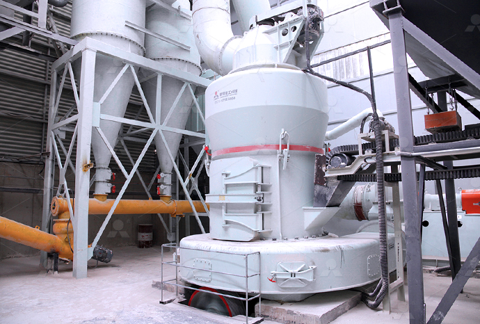
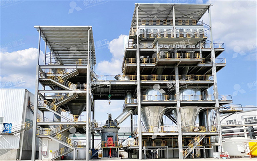
MTW European Type Trapezium Mill
Input size:30-50mm
Capacity: 3-50t/h
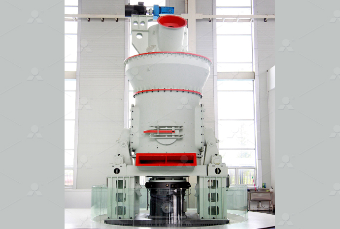
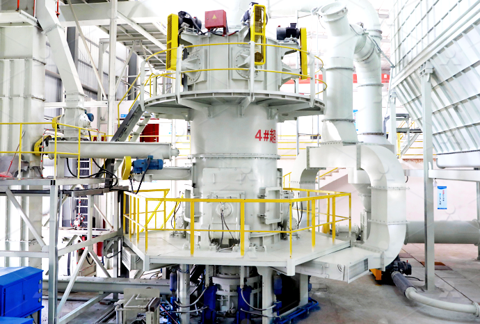
LM Vertical Roller Mill
Input size:38-65mm
Capacity: 13-70t/h
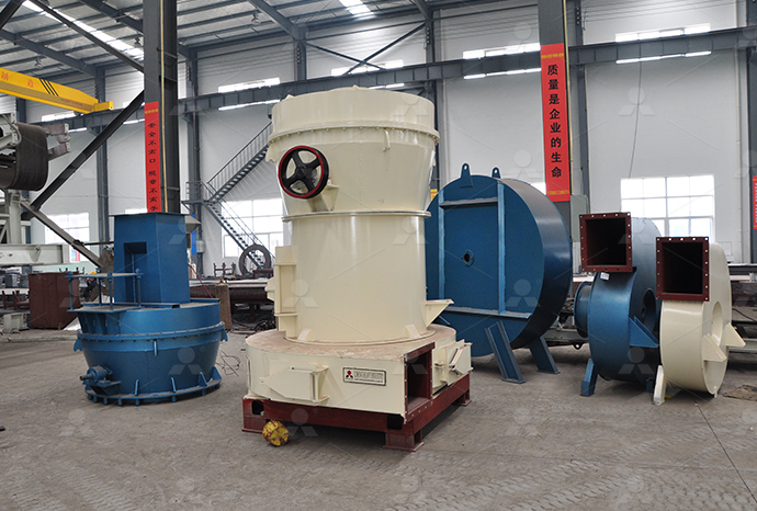
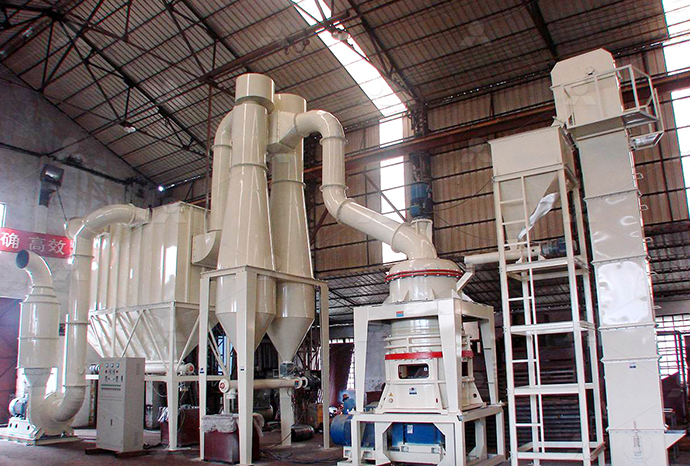
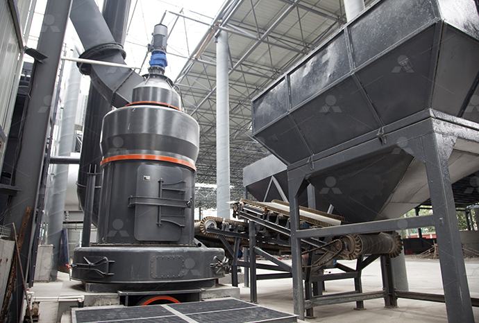
Raymond Mill
Input size:20-30mm
Capacity: 0.8-9.5t/h
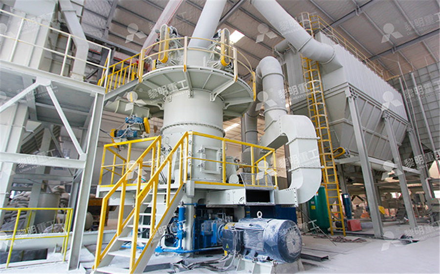
Sand powder vertical mill
Input size:30-55mm
Capacity: 30-900t/h
LUM series superfine vertical roller grinding mill
Input size:10-20mm
Capacity: 5-18t/h
MW Micro Powder Mill
Input size:≤20mm
Capacity: 0.5-12t/h

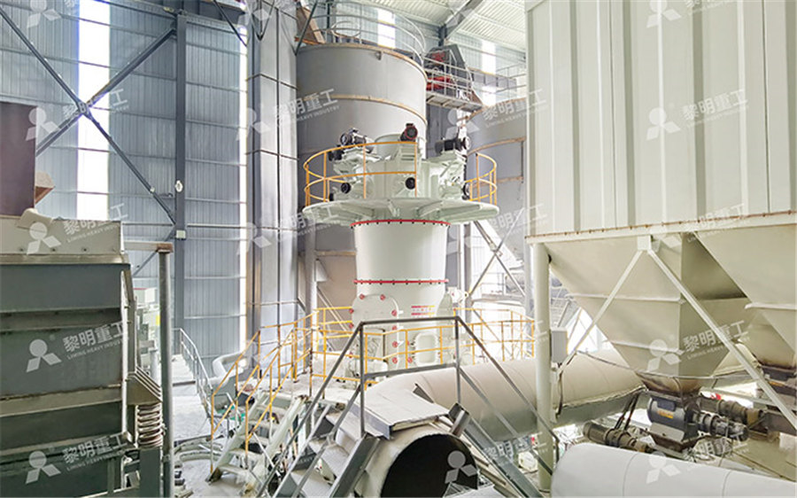
LM Vertical Slag Mill
Input size:38-65mm
Capacity: 7-100t/h
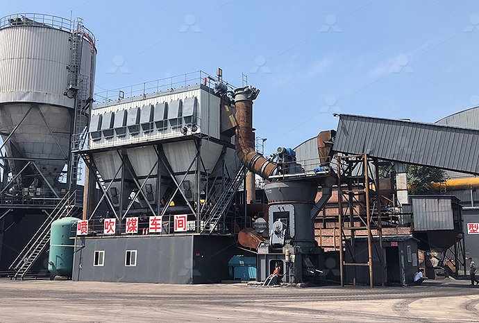
LM Vertical Coal Mill
Input size:≤50mm
Capacity: 5-100t/h
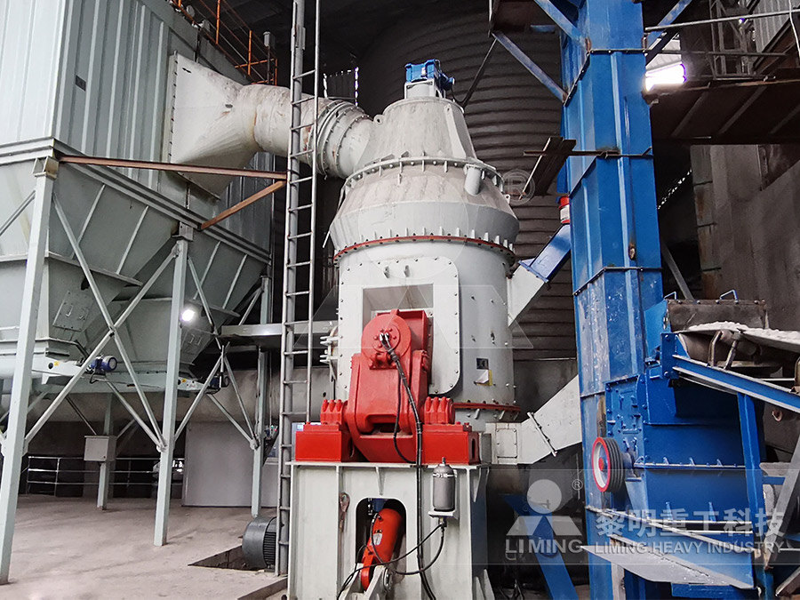
TGM Trapezium Mill
Input size:25-40mm
Capacity: 3-36t/h
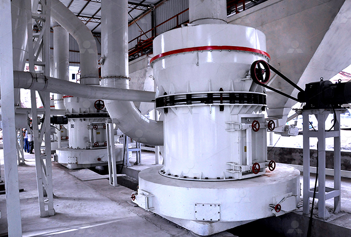
MB5X Pendulum Roller Grinding Mill
Input size:25-55mm
Capacity: 4-100t/h
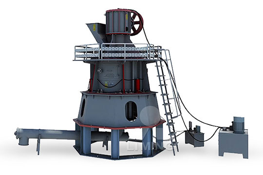
Straight-Through Centrifugal Mill
Input size:30-40mm
Capacity: 15-45t/h
Cam divider jitter problem
.jpg)
[原创] 关于divider的noise与jitter的转换 EETOP
2016年9月22日 从电路分析,如果输入源没有jitter积累,synchronize divider之后的时钟,其jitter应该不变。 如果divider的输入为VCO的输出,那么jitter应该有积累,但是从公式推导得到 mitigate jitter accumulation, a retiming block, including a FlipFlop (DFF) and a buffer, is applied, labeled as “Retimer” in Fig 1(a) The “Retimer” block resamples the output with the input A CMOS High Speed MultiModulus Divider With Retiming for Abstract: A new asynchronous high speed multimodulus divider (MMD) architecture is presented in this letter This new architecture significantly reduces the delay of the critical path, which not A CMOS High Speed MultiModulus Divider With Retiming for Divider Circuit Style Partitioning • CML dividers operate at the highest speed, but their static power consumption reduces efficiency at lower speeds • For large divide ratios, a mixture of ECEN620: Network Theory Broadband Circuit Design Fall 2024
Jitter and phase noise in frequency dividers IEEE Xplore
Jitter and phase noise in frequency dividers Abstract: Repeats short, earlier investigations dealing with the noise properties of digital frequency dividers (FDs), compares these results with later Advantage: low jitter (explained shortly) Problems: high power (all registers run at high frequency), high loading on clock (IN signal drives all registers)High Speed Frequency Dividers CppSim2018年9月27日 To minimize skew, balance clock paths using Htree or matchedtree clock distribution structures If possible, route data and clock in opposite directions; eliminates races Lecture 9: Clocking, Clock Skew, Clock Jitter, Clock Distribution and ISI, sometimes called data dependent jitter, is usually the result of a bandwidth limitation problem in either the transmitter or physical mediaJitter—Understanding it, Measuring It, Eliminating It; Part 3: Causes
.jpg)
Jitter analysis of digital frequency dividers in communication
Jitter in frequency dividers can lower the MIPS rating in digital signal processors or increase the bit error rate in digital communication systems In this paper, a new method of analysing jitter In this paper, the problem of jitter in clock recovery circuits will be studied and analyzed The main objective is to develop an improved dejitter circuit that may add some features to the already existing VCXO technique Index Terms—Jitter, oscillator noise, oscillator stability, phase jitter, phase locked loops, phase noise, voltage Low Jitter Circuits in Digital System using Phase Locked Loop2002年10月24日 Low Jitter Design of a 035 µ mCMOS Frequency Divider Operating up to 3GHz L Romanò, S Levantino, S Pellerano, C Samori, A Lacaita Dipartimento di Elettronica ed Informazione, Politecnico Low jitter design of a 035µm–CMOS frequency to synchronous ones Jitter performance is another concern for MMDs If the output is drawn from the MMD’s divided result,shownasOUT’inFig1(a), the jitter contributed by each divider and the associated control gates is accumulated and degrades the output signal phase noise performance To mitigate jitter accumulation, a retiming block A CMOS High Speed MultiModulus Divider With Retiming for Jitter
¿Qué es el jitter? Definición y medidas preventivas IONOS
2023年3月2日 Las causas de aparición del jitter pueden variar Básicamente, pueden darse las siguientes: Hardware o infraestructura de red de baja calidad: el jitter de la red puede producirse cuando se utilizan routers, módems, ordenadores, cables, conmutadores o periféricos obsoletosLas señales se retrasan durante la transmisión y los comandos solo se ejecutan 2004年9月15日 Inserting a resistor isnt a problem as long as supplies are tidy, devices are adequately decoupled, and the value is kept no bigger than around 470R (I have used 100R with no worsening of jitter) However a trick those with a power electronics background (like myself) use frequently is to 'swamp' the Cbe/Cgs with a small external capacitorjitter introduced by divider chips diyAudio2007年1月8日 Re: devider jitters Hi echo47, thanks! It's really a signal integrity problem! I disabled my oscillator of 'osc' and feed in with a SG,then, all things go all right my oscillator is made of CMOS invertors the wave is smooth on the oscilligraph(BW=200M,SR=1G) because I used shuntcap at 'osc' node but still has phasejitter maybe this phase jitter caused weird Problem with clk jitters in a 1/4 divider Forum for Electronics2013年10月1日 High speed divider is highly desired in the millimeter wave (mmW) frequency synthesizer design A high operating frequency, low power consumption 90nm CMOS programmable pulse swallow multi A CMOS High Speed MultiModulus Divider With Retiming for Jitter
Can a frequency Divider cause Jitter? diyAudio
2003年12月10日 Some Clock's use a frequency divider IC after the clock, to save money by only stocking 23 different frequencies The other 8 freqencies required to cover all CD / DVD models can then be derived from the 3 fundamental frq's, by diving, for example: 338688 MHz (Fundamental oscilator freq) div by 2 = 169344 MHz div by 2 = 84672 MHz div by 2 = 42336 Divider VCO ref(t) div(t) ref(t) v(t) out(t) 2 MH Perrott Divideby2 Circuit (Johnson Counter) Advantage: low jitter (explained shortly)Problems: high power (all registers run at high frequency), high loading on clock (IN signal drives all registers) Tclk IN OUT Tclk Tclk 1 A B IN OUT A BHigh Speed Frequency Dividers CppSim8 Jitter 24 81 Jitter Metrics 25 82 Types of Jitter 26 9 Synchronous Jitter 27 91 Extracting Synchronous Jitter 29 10 Accumulating Jitter 31 101 Extracting Accumulating Jitter 32 11 Jitter of a PLL 35 12 Modeling a PLL with Jitter 35 121 Modeling Driven Blocks 35 122 Modeling Accumulating Jitter 37 123 VCO Model 38Predicting the Phase Noise and Jitter of PLLBased Frequency 2005年3月25日 clock divider jitter Thanks for the responses My question regarding jitter effects has the following reason: I was wondering whether multirate cascaded (MASH) sigma delta modulators might benefit from a slower clock in the first stage and higher clock in the second stage VS a 2nd order modulator single loop at a high clock rateclock divider jitter Forum for Electronics
.jpg)
pnoise jitter and pnoise time average discrepency:
2020年2月14日 When I simulate my circuit with the pnoise/jitter method, I get a RMS Jitter in a given bandwidth of 594386fs (Jee>RMS) And when I simulate with the pnoise/time average method, by calculating my Jitter from the Phase 2023年3月2日 Le cause del jitter possono essere diverse a seconda dei casi In generale possono essere le seguenti: Scarsa qualità dell’hardware o dell’infrastruttura di rete: il jitter sulla rete può verificarsi in caso di utilizzo di router, modem, computer, cavi, switch o periferiche di tipo obsoleto I segnali subiscono rallentamenti durante la trasmissione e i comandi vengono Che cos’è il jitter? Definizione e spiegazione IONOSunusual design or the problems with existing design As we discussed in [1], the phase noise or a noise during a transition when a signal is sampled by a threshold will lead to a jitter In communication system it will nega tively impact the transmission quality Jitter generation by the circuit, jitter transfer by the circuit and jitterApplication Note PLL jitter measurements University of Delaware2013年4月11日 A new asynchronous high speed multimodulus divider (MMD) architecture that significantly reduces the delay of the critical path, which not only pushes to ultrahigh speed operation, but also allows retiming techniques to suppress jitter accumulation from the divider chain simultaneously A new asynchronous high speed multimodulus divider (MMD) A CMOS High Speed MultiModulus Divider With Retiming for Jitter
.jpg)
Multimodulus divider retiming circuit Google Patents
A multimodulus divider (MMD) receives an MMD input signal and outputs an MMD output signal SOUT The MMD includes a chain of modulus divider stages (MDSs) Each MDS receives an input signal, divides it by either two or three, and outputs the result as an output signal Each MDS responds to its own modulus control signal that controls whether it divides by two or three2012年10月15日 The simplified dividerless ADPLL has a reduced phase difference at the input of the phasefrequency detector, avoiding a lengthy power hungry timetodigital converter (TDC) The ADPLL consumes 15mW of power and has a measured integrated RMS jitter 019ps from 10kHz to 40MHz frequency offset at 15GHz carrier frequencyA 15GHz 02psRMS jitter 15mW dividerless FBAR ADPLL in The lowfrequency jitter can be found by subtracting the alignment jitter from the timing jitter This will yield accurate results for most types of jitter, such as sinusoidal or random sources of jitter If the jitter source is a complex waveform, such as a square wave, the frequency and duty cycle will have an effect on this calculationJitter Characteristics and Measurements Society of Motion 2020年6月11日 As long as the divider is using only one edge of the input clock, and only one edge of the output clock is being used by the ADC, then no, there will be no significant increase in jitter The output edges will have the same peaktopeak jitter as the input edges, in terms of absolute time (ps or ns)adc Does dividing a clock increase its jitter? Electrical
Design Challenges for an UltraLowJitter Clock Synthesizer
The divider adds jitter and is, therefore, placed within the PLL loop to take advantage of noise shaping The loop filter is lowpass for reference noise Above 10kHz phase noise is no problem, assuming that nothing else degrades it Recall that the phasenoise requirements were derived for a 2GHz oscillator Figure 3, however, shows the Jitter in Asynchronous vs Synchronous Dividers 21 Asynchronous Synchronous • Jitter accumulates with the clocktoQ delays through the divider • Extra divider delay can also degrade PLL phase margin • Divider output is “sampled” with high frequency clock • Jitter on divider clock is similar to VCO output • Minimal divider delay DQ ECEN620: Network Theory Broadband Circuit Design Fall 年8月14日 PDF The design of a 32/33 frequency divider, that can operate with input frequency up to 3GHz is discussed The circuit is realized in a 0351m CMOS Find, read and cite all the research you (PDF) Low Jitter Design of a 035µmCMOS Frequency Divider Operating 2023年6月13日 Momentane JitterMessung – verwenden Sie diese Technik, wenn Sie beide Endpunkte steuern Es bedeutet einfach die Differenz zwischen Sende und Empfangsintervallen für ein einzelnes Paket Hier ist Jitter die mittlere Varianz zwischen Messungen des momentanen Jitters und dem mittleren momentanen Jitter über die Übertragung mehrerer PaketeWas ist Jitter? Typische Ursachen und Möglichkeiten zur
.jpg)
Character in FixedUpdate() and Camera in LateUpdate() Jitter Problem
2016年1月19日 I’ve modeled my third person controller using this structure (character, rigidbody, moves from FixedUpdate() and Camera moves in LateUpdate()) and everything is running absolutely smoothly However, I’ve included a firstperson mode in which the camera rotates up and down on it’s ‘transformright’ and rotates left to right on ‘Vector3up’ I position the camera 2013年4月11日 A new asynchronous high speed multimodulus divider (MMD) architecture is presented in this letter This new architecture significantly reduces the delay of the critical path, which not only pushes to ultrahigh speed operation, but also allows retiming techniques to suppress jitter accumulation from the divider chain simultaneously A prototype in a 65 nm A CMOS High Speed MultiModulus Divider With Retiming for Jitter CAMDEX brand cam indexer, 20 years of production and design experience, precise positioning, high speed without jitter, direct drive motor, professional manufacturer of linear motor +86 liene@cncamdexCam indexer manufacturers, Direct drive motor, Linear Motor 2021年7月25日 Hello, So I’ve been using cinemachine freelook for my game I’m building Its a 3rd person camera Now I recently switched my movement from character controller to rigidbody, and that’s when I started having jitter issues Now I understand that rigidbody uses fixed update for updating the player movement I’ve tried going though many of the different cine machine Cinemachine jitter problem Unity Engine Unity Discussions
Behavioral Modeling and Simulation of Jitter and Phase Noise
From [4] we can find the relationship of jitter and signal phase noise is ( ) 2 2 2 4 2 1 2 c m c m a f L f a p f × = × + (10) 23 Jitter after an NDivider If we consider a signal with frequency f 1 after an N divider, the output signal will be at the frequency of f With these values it turns out (3) that σ∆T≅100fs rms The 2/3 divider is instead scaled up by a factor of 3: the unloaded capacitance is thus 3C0, giving a CT=6C0 total output capacitance Since the bias current is 3IB=750µA, the jitter of the 2/3 divider is approximately σ2∆T/6=017σ2∆T(PDF) Low jitter design of a 035µm–CMOS frequency divider In this paper, the problem of jitter in clock recovery circuits will be studied and analyzed The main objective is to develop an improved dejitter circuit that may add some features to the already existing VCXO technique Index Terms—Jitter, oscillator noise, oscillator stability, phase jitter, phase locked loops, phase noise, voltage Low Jitter Circuits in Digital System using Phase Locked Loop2002年10月24日 Low Jitter Design of a 035 µ mCMOS Frequency Divider Operating up to 3GHz L Romanò, S Levantino, S Pellerano, C Samori, A Lacaita Dipartimento di Elettronica ed Informazione, Politecnico Low jitter design of a 035µm–CMOS frequency
A CMOS High Speed MultiModulus Divider With Retiming for Jitter
to synchronous ones Jitter performance is another concern for MMDs If the output is drawn from the MMD’s divided result,shownasOUT’inFig1(a), the jitter contributed by each divider and the associated control gates is accumulated and degrades the output signal phase noise performance To mitigate jitter accumulation, a retiming block 2023年3月2日 Las causas de aparición del jitter pueden variar Básicamente, pueden darse las siguientes: Hardware o infraestructura de red de baja calidad: el jitter de la red puede producirse cuando se utilizan routers, módems, ordenadores, cables, conmutadores o periféricos obsoletosLas señales se retrasan durante la transmisión y los comandos solo se ejecutan ¿Qué es el jitter? Definición y medidas preventivas IONOS2004年9月15日 Inserting a resistor isnt a problem as long as supplies are tidy, devices are adequately decoupled, and the value is kept no bigger than around 470R (I have used 100R with no worsening of jitter) However a trick those with a power electronics background (like myself) use frequently is to 'swamp' the Cbe/Cgs with a small external capacitorjitter introduced by divider chips diyAudio2007年1月8日 Re: devider jitters Hi echo47, thanks! It's really a signal integrity problem! I disabled my oscillator of 'osc' and feed in with a SG,then, all things go all right my oscillator is made of CMOS invertors the wave is smooth on the oscilligraph(BW=200M,SR=1G) because I used shuntcap at 'osc' node but still has phasejitter maybe this phase jitter caused weird Problem with clk jitters in a 1/4 divider Forum for Electronics
A CMOS High Speed MultiModulus Divider With Retiming for Jitter
2013年10月1日 High speed divider is highly desired in the millimeter wave (mmW) frequency synthesizer design A high operating frequency, low power consumption 90nm CMOS programmable pulse swallow multi 2003年12月10日 Some Clock's use a frequency divider IC after the clock, to save money by only stocking 23 different frequencies The other 8 freqencies required to cover all CD / DVD models can then be derived from the 3 fundamental frq's, by diving, for example: 338688 MHz (Fundamental oscilator freq) div by 2 = 169344 MHz div by 2 = 84672 MHz div by 2 = 42336 Can a frequency Divider cause Jitter? diyAudioDivider VCO ref(t) div(t) ref(t) v(t) out(t) 2 MH Perrott Divideby2 Circuit (Johnson Counter) Advantage: low jitter (explained shortly)Problems: high power (all registers run at high frequency), high loading on clock (IN signal drives all registers) Tclk IN OUT Tclk Tclk 1 A B IN OUT A BHigh Speed Frequency Dividers CppSim