


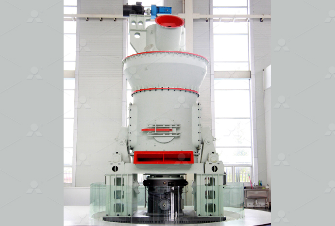
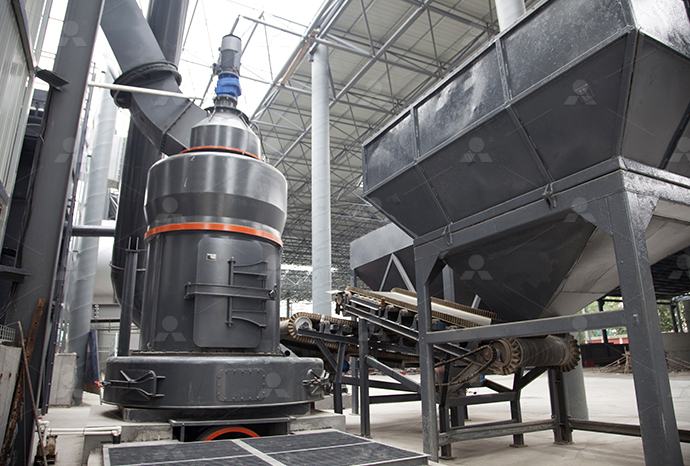
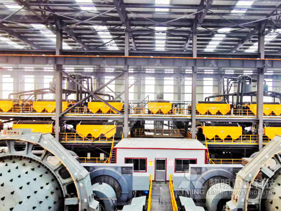
MTW European Type Trapezium Mill
Input size:30-50mm
Capacity: 3-50t/h
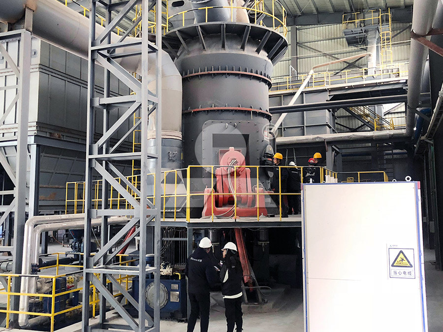
LM Vertical Roller Mill
Input size:38-65mm
Capacity: 13-70t/h
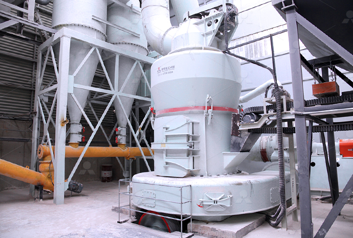
Raymond Mill
Input size:20-30mm
Capacity: 0.8-9.5t/h
Sand powder vertical mill
Input size:30-55mm
Capacity: 30-900t/h
LUM series superfine vertical roller grinding mill
Input size:10-20mm
Capacity: 5-18t/h
MW Micro Powder Mill
Input size:≤20mm
Capacity: 0.5-12t/h

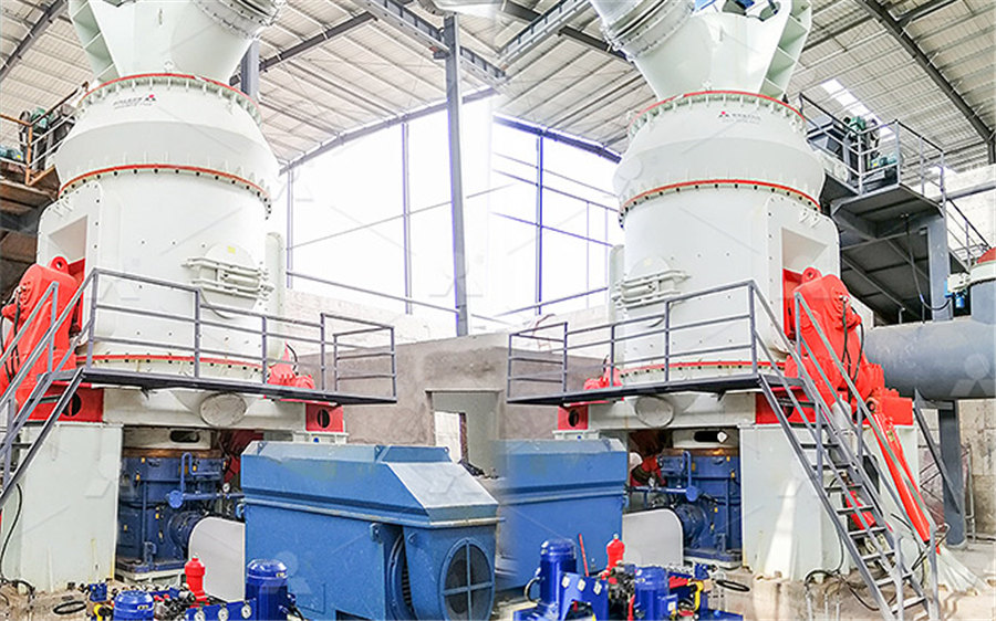
LM Vertical Slag Mill
Input size:38-65mm
Capacity: 7-100t/h
LM Vertical Coal Mill
Input size:≤50mm
Capacity: 5-100t/h
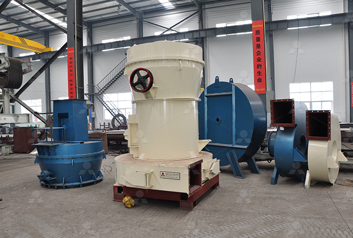
TGM Trapezium Mill
Input size:25-40mm
Capacity: 3-36t/h
MB5X Pendulum Roller Grinding Mill
Input size:25-55mm
Capacity: 4-100t/h
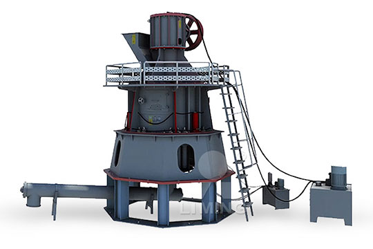
Straight-Through Centrifugal Mill
Input size:30-40mm
Capacity: 15-45t/h
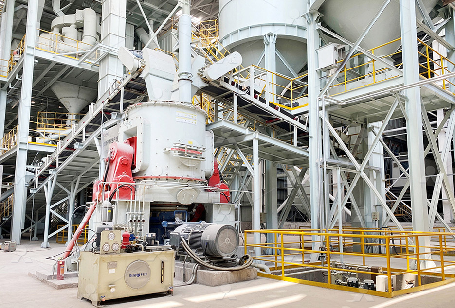
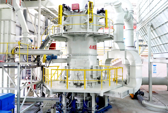
Wiring diagram of control cabinet of large dolomite industrial mill
Electrical Drawings, Schematics, and Wiring Diagrams: How to
2024年1月15日 The idea of the electrical or wiring diagram is to trace the flow of power and signals between the sources, control devices, and final loads These will usually be drawn in a 5 天之前 In this article, you’ll find a rundown of the different types of PLC Cabinets, tips on layout and wiring, and an exploration of the key components within these cabinets We’ll also share Guide to PLC Cabinets: Types, Layout, Wiring Componentscontrol particular aspects of safety at work These regulations, which must be complied with, are often produced because of European Directives, which in turn are designed to harmonise the Industrial Control Wiring GuideBASIC WIRING PRACTICES * Wire: Use all 600V 90 Deg C rated wire Use stranded wire Use MTW type wire Note any exceptions so these can be added to the drawings or design notes * Control Panel Layout And Wiring Best Practices IDCOnline
.jpg)
CONTROL CABINET WIRING RS Components
This guide will give you and overview of the most popular RS PRO parts for professional wiring of a control cabinet Starting from bootlace ferrules to the right stripping and crimping tools, to Construct control cabinets in a fraction of the time through simple manual wiring without tools: WAGO Pushin CAGE CLAMP ® Technology allows you to reduce costs, increase the safety Control Cabinet – Wiring WAGO2020年8月16日 Wires and preparation for control wiring Electrical equipment uses a wide variety of wire and cable types and it is up to us to be able to correctly identify and use the Industrial control wiring and cabling guide EEPThe circuit diagram for your CNC machining centre is created by our inhouse electrical design team and implemented by our electrical department Once the basic control cabinet has been Electrical Department CNC milling machines HG GRIMME SysTech
.jpg)
Fix Control Cabinet Connectivity and Wiring Issues TE Connectivity
Learn about how TE can help you solve many of the control cabinet connectivity and wiring issues We offer an extensive product portfolio to address the requirements specific to 2013年1月16日 Fig 2 presents the technological diagram of gristing phase of the wheat in an industrial mill with the capacity of 220 t/24 h Milling unit consists of 9 double roller mills, of which the first Grinding Characteristics of Wheat in Industrial MillsRead about Electrical Signal and Control Wiring (Instrument Connection and Communication) are popular examples Most industrial field wiring connections utilize a combination of compressionstyle crimp “lugs” Capacitive coupling Electrical Signal and Control WiringChapter 3: Pellet Mill Design drive, thus providing longer overall service life than a belt drive The highlyvariable loads which can occur in a pellet mill can generate overload conditions Stalled conditions are usually caused by the die plugging and/or trying to start the mill under load GearPellet mill design Feed Strategy
.jpg)
Industrial Control Panel Design Standards and Best Practices
2022年9月27日 In the previous article, we covered the steps required to design an industrial control panel successfully This article will go deeper into some control panel design concepts, focusing on standards and regulations and some of the industry's best practices, including NFPA 70 and 79, IEC/ UL 6, and UL 508 Figure 12017年6月21日 Wiring tips Connections routing Wiring industrial control panels is a complex process and it needs a number of carefully planned and performed details However, there are dozen of tips and advices on how to do this and that, but this technical article will limit to wire connections and routing inside of control panelsWiring tips for connections and routing inside industrial control Construct control cabinets in a fraction of the time through simple manual wiring without tools: WAGO Pushin CAGE CLAMP ® Technology allows you to reduce costs, increase the safety of your application and reduce the time and effort for control cabinet wiring by up to 50 percentControl Cabinet – Wiring WAGOThis wiring diagram provides a valuable tool for troubleshooting, maintenance, and upgrades, ensuring that the mill remains in optimal condition for years to come Power Supply In the context of a Bridgeport mill wiring diagram, the power supply is a crucial component that provides the necessary electrical energy to operate the machineThe Ultimate Guide to Bridgeport Mill Wiring Diagram:
Everything You Need to Know About Wiring Diagram SmartDraw
Customize hundreds of electrical symbols and quickly drop them into your wiring diagram Special control handles around each symbol allow you to quickly resize or rotate them as necessary To draw a wire, simply click on the Draw Lines option on the left hand side of the drawing areaIndustrial Control Panels and Electrical Equipment of Industrial Machinery for North America A Guide for Practical Use Reference Manual 08/2014 A5EA/RSAA/002 Disclaimer of Liability 1 2 115 Wiring practice Reference Manual Industrial Control Panels and ElectricalLarge Control Panel Wiring Example The quality of the wiring methods used in an industrial control panel can vary quite widely This article summarizes what this author believes are some best practice when it comes to * Wiring Control Wires: Use Control Panel Layout And Wiring Best Practices IDCOnlineA wiring diagram can also be useful in auto repair and home building projects For example, the proper location of light fixtures and electrical outlets can be easily by a home builder to avoid costly defaults or building any code violations Wiring Diagram – A Comprehensive Guide
.jpg)
Industrial control wiring and cabling guide EEP
2020年8月16日 Industrial control wiring guide (photo credit: nilza) Such factors include: The insulation material; The size of the conductor; What it’s made of; Whether it’s solid or stranded and flexible These are all considerations UnderstandingControlWiringDiagramsIntropdf Transcript: [0m:4s] Hi I'm Josh Bloom, These videos will focus specifically on wiring diagrams that are related to industrial control and what you might encounter when laying out schematics for a control panel that include power and signal drawingsUnderstanding Control Wiring Diagrams Intro RSP SupplyWAGO’s TOPJOB ® S RailMount Terminal Blocks are available with levers, pushbuttons and operating slots, offering the right solution for any wiring task Thanks to Pushin CAGE CLAMP ® technology for all terminals blocks, wiring is quick and easy ADVANTAGES: Railmount terminal blocks with levers allow toolfree termination and removal of all conductor types by handControl Cabinet – Wiring WAGO India2022年6月18日 Layout Structure Design of PLC Control Cabinet The PLC control cabinet refers to the programmable control cabinet,and the if the output port of your PLC is powered at 24VDC, but the diagram drawn in your control loop requires the node supplied by the PLC to be 220VAC, then you PLC electrical control cabinet wiringLayout Structure Design of PLC Control Cabinet (A)
.jpg)
How to Read a PLC Wiring Diagram? Upmation
In Part 1 of this series, you’ve learned how to read and understand a wiring diagram of an industrial control panel and in this Part, we’re going to continue with the PLC part of that same control panel In this article, you’ll learn about the PLC and its modules’ wiring diagramAutomatic StarDelta Starter (YΔ) Using Timer for 3Phase Induction Motor Schematic Power, Control, PLC Ladder and Wiring Diagrams How to Wire a StarDelta Starter with s very inportant circuit for industrial aria Reply Nasir Uddin I once worked on a Large Burnt out 3 Phase Motor which was used for pumping sugar from the Automatic Star Delta Starter Power, Control Wiring Diagram2022年9月19日 Join us here, get awesome perks, and support us, all at once:https://youtube/c/upmation/joinBefore you watch this video, we suggest watching the prWiring Diagram Structure of a RealWorld CustomMade 2023年5月15日 For industrial applications built to UL508A specifications, this guideline for industrial control panels suggests colors for the positive (+) and negative () 24 V DC signals In these cases, including PLC input and output conductors, all (+) 24 V wires should be blue, and all () 24 V wires should be white with a blue stripeUnderstanding Wire Color Codes for Industrial Electrical
.jpg)
Basic Wiring for Motor Contol
The control circuit is separate from the motor circuit The control circuit may not be at the same voltage as the power circuit When the voltage of the control and power circuits is the same, it is referred to as Common Control If the voltages are different, it is called Separate Control Figure 4 Typical Starter Wiring Diagram — ThreePhaseLearn about the distinctions between various diagram types (Ladder, Schematic, and Wiring Diagrams) commonly used in electrical engineering: Ladder Diagrams: These graphical representations showcase control circuits and relay logic in Types of Electrical Diagrams Electrical Ladder, ways There is a “wiring diagram” and adjacent to it a “line diagram” Line diagrams are included because their use is becoming more widespread and we believe it is advantageous to learn to use them Wiring diagrams or connection diagrams include all GI20: Typical Wiring Diagrams Rockwell AutomationComplete your drilling project effortlessly and rapidly with the selection of this excellent Grizzly Industrial Mill and Drill with tapered gibs with double locks Large 71/16 in x 265/8 in table This is an excellent value and great for just Grizzly Industrial Mill/Drill with Stand and DRO G0759
Process control variables, instrumentation and automation of
With an understanding of the control parameters and how they are monitored electronically, the basic methods used to apply this instrumentation to automatically control a pellet mill will then be discussed Finally, emerging trends and technology that will determine the direction of future systems will be shown Control variablesThis document provides information about industrial electrical control and wiring diagram manuals It discusses where to find these manuals online in electronic formats like PDF While some websites store the full manuals, this document explains that their website provides references to where the manuals can be downloaded or read online They have these Industrial Electrical Control and Wiring Diagram Manuals2020年3月10日 PLC and DCS control systems Wiring Diagrams for Digital Input (DI), Digital Output (DO), Analog Input (AI), and Analog Output We are NOT using any additional power supply in the marshaling cabinet (or at the control room side), Industrial Control Systems; Difference between DCS PLC; Control System Security;Wiring Diagrams of PLC and DCS Systems DI, DO, AI, AO Inst by Simcona on Sep 12, 2023 9:39:04 AM It’s not just the product – it’s also how you use it There are many right and wrong ways to wire an industrial control panel according to NEC (National Electric Code) standardsSure, the specs of the wire itself matter (and we’ll cover them below), but layout and safety planning are arguably even more important8 Control Panel Wiring Guidelines for Industrial Electronics
.jpg)
Emill – Springwood Industrial, Inc ACER Online
Emill™ Head Wiring Diagram User Manual Emill™ 3VK 5VK Milling Head Manual 2015 Version Manual Control Panel Layout12; Downloads; Tech Support Files; User Manuals; Parts Manuals; Videos Machine Introduction Videos; Springwood Industrial, IncExplore PLC wiring diagram examples to learn the basics of connecting and programming a PLC system for industrial automation Skip to content Logic Controller, is a digital computer used for automation of various electromechanical processes It is designed to control machinery and automate industrial processes Uncategorized Post navigation5 Practical PLC Wiring Diagram Examples for BeginnersElectrical panel wiring diagrams are used to outline each device, as well as the connection between the devices found within an electrical panel As electrical panels are what will contain control systems, panel wiring diagrams are commonly encountered by PLC technicians and engineers Although electrical panels may not be overly complex from the first glance, a lot of Electrical Panel Wiring Diagram SolisPLC2013年1月16日 Fig 2 presents the technological diagram of gristing phase of the wheat in an industrial mill with the capacity of 220 t/24 h Milling unit consists of 9 double roller mills, of which the first Grinding Characteristics of Wheat in Industrial Mills
Electrical Signal and Control Wiring
Read about Electrical Signal and Control Wiring (Instrument Connection and Communication) are popular examples Most industrial field wiring connections utilize a combination of compressionstyle crimp “lugs” Capacitive coupling Chapter 3: Pellet Mill Design drive, thus providing longer overall service life than a belt drive The highlyvariable loads which can occur in a pellet mill can generate overload conditions Stalled conditions are usually caused by the die plugging and/or trying to start the mill under load GearPellet mill design Feed Strategy2022年9月27日 In the previous article, we covered the steps required to design an industrial control panel successfully This article will go deeper into some control panel design concepts, focusing on standards and regulations and some of the industry's best practices, including NFPA 70 and 79, IEC/ UL 6, and UL 508 Figure 1Industrial Control Panel Design Standards and Best Practices2017年6月21日 Wiring tips Connections routing Wiring industrial control panels is a complex process and it needs a number of carefully planned and performed details However, there are dozen of tips and advices on how to do this and that, but this technical article will limit to wire connections and routing inside of control panelsWiring tips for connections and routing inside industrial control
.jpg)
Control Cabinet – Wiring WAGO
Construct control cabinets in a fraction of the time through simple manual wiring without tools: WAGO Pushin CAGE CLAMP ® Technology allows you to reduce costs, increase the safety of your application and reduce the time and effort for control cabinet wiring by up to 50 percentThis wiring diagram provides a valuable tool for troubleshooting, maintenance, and upgrades, ensuring that the mill remains in optimal condition for years to come Power Supply In the context of a Bridgeport mill wiring diagram, the power supply is a crucial component that provides the necessary electrical energy to operate the machineThe Ultimate Guide to Bridgeport Mill Wiring Diagram: Customize hundreds of electrical symbols and quickly drop them into your wiring diagram Special control handles around each symbol allow you to quickly resize or rotate them as necessary To draw a wire, simply click on the Draw Lines option on the left hand side of the drawing areaEverything You Need to Know About Wiring Diagram SmartDrawIndustrial Control Panels and Electrical Equipment of Industrial Machinery for North America A Guide for Practical Use Reference Manual 08/2014 A5EA/RSAA/002 Disclaimer of Liability 1 2 115 Wiring practice Reference Manual Industrial Control Panels and Electrical
.jpg)
Control Panel Layout And Wiring Best Practices IDCOnline
Large Control Panel Wiring Example The quality of the wiring methods used in an industrial control panel can vary quite widely This article summarizes what this author believes are some best practice when it comes to * Wiring Control Wires: Use