


MTW European Type Trapezium Mill
Input size:30-50mm
Capacity: 3-50t/h
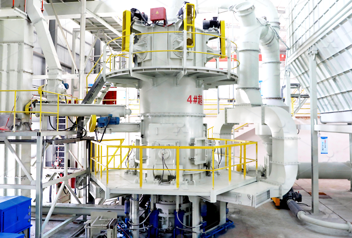
LM Vertical Roller Mill
Input size:38-65mm
Capacity: 13-70t/h
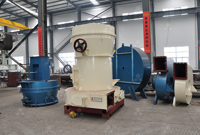
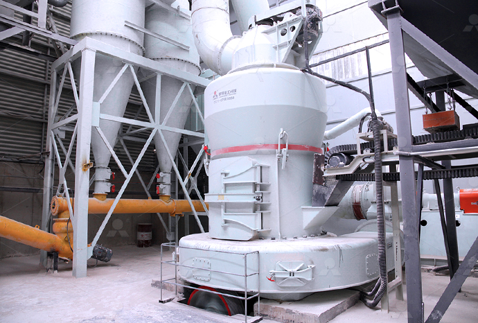
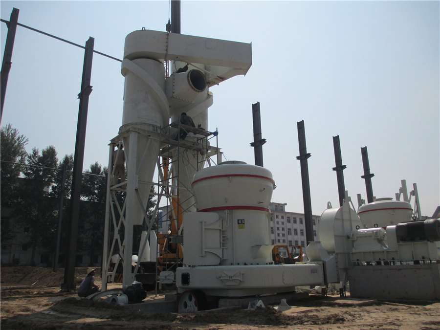
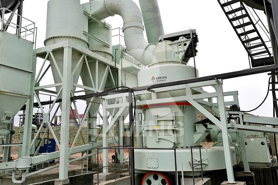
Raymond Mill
Input size:20-30mm
Capacity: 0.8-9.5t/h

Sand powder vertical mill
Input size:30-55mm
Capacity: 30-900t/h
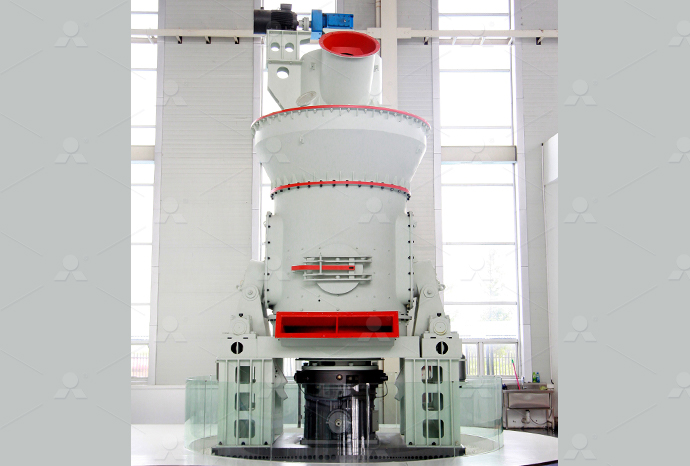
LUM series superfine vertical roller grinding mill
Input size:10-20mm
Capacity: 5-18t/h
MW Micro Powder Mill
Input size:≤20mm
Capacity: 0.5-12t/h

LM Vertical Slag Mill
Input size:38-65mm
Capacity: 7-100t/h

LM Vertical Coal Mill
Input size:≤50mm
Capacity: 5-100t/h
TGM Trapezium Mill
Input size:25-40mm
Capacity: 3-36t/h
MB5X Pendulum Roller Grinding Mill
Input size:25-55mm
Capacity: 4-100t/h
Straight-Through Centrifugal Mill
Input size:30-40mm
Capacity: 15-45t/h
Ore mill electrical schematic diagram
SAG Mill Grinding Circuit Design 911Metallurgist
The design of large mills has become increasingly more complicated as the size has increased and there is little doubt that without sophisticated 展开Advanced knowledge of ore hardness before AG/SAG milling, therefore, provides better preconditioning steps such as blending of different feed ores to maximise mill performance throughSchematic diagram of AG/SAG mill process 2015年7月28日 Simple 1 “Closed Circuit” Ball Mill with Cyclone Grinding Circuit/Flowsheet This is the path that the ore takes in this circuit The ore comes from the fine ore storage area to be Simple Grinding Circuits Flowsheets 911MetallurgistMilling is among the most energyconsuming technological stages of copper ore processing It is performed in mills, which are machines of high rotational masses The start of a millSchematic diagram of the drive system allowing the use of a fluid
Process flow diagram of the primary ROM ball milling
Anglo Platinum's control schema for a RunofMine (ROM) ball milling comminution circuit follows a layered approach that involves basic control (regulatory, interlock and sequence control), fuzzyThe ball mill grinding process is mainly composed of a ball mill, a hydrocyclone cluster, a sump, a slurry pump and an ore bin The schematic diagram of this process is shown in Fig 1 Fig 1 Intelligent optimal control system for ball mill grinding process2007年1月1日 There are various types of interconnections between mills and classifiers Figure 1 shows a schematic diagram of an open and closedcircuit system When a mill is operated Chapter 20 Modelling of Mills and Milling CircuitsThis paper addresses the critical design parameters as well as the consideration of ore characteristics, geographical location, climatic conditions, expected operational life, expansion Crushing Plant Design and Layout Considerations 911 Metallurgist
.jpg)
Schematic diagram of the drive system allowing the use of a fluid
Download scientific diagram Schematic diagram of the drive system allowing the use of a fluid coupling for mill startup: 1asynchronous motor 630 kW 1000 RPM, 2fluid coupling, 3gearbox, 4 all schematics Schematic Diagrams Schematic diagrams document the connection points and construction methods of electrical and electronic circuits Figure 1shows a simple schematic diagram of a power supply; on it you can see some of the conventions used Figure 2 shows the symbols for such basic components as wires and Understanding and UsingStudy Unit Understanding and Using Electronic Diagrams2015年7月28日 The ore is simply brought from the fine ore storage area and run into one end of the grinding machine called a MILL, the mill grinds it and mixes it into a slurry which is sent to the next stage of processing Simple “Open Circuit” 1 Ball Mill Grinding Circuit/Flowsheet Our second flow sheet, has a couple extra pieces of equipment addedSimple Grinding Circuits Flowsheets 911Metallurgist2024年6月28日 Introduction In the world of electronics and engineering, the ability to read and interpret schematics is a fundamental skill But what exactly are schematics, and why are they so important? Schematics, or circuit diagrams, are visual representations of electronic circuitsThey use symbols to represent different electronic components and show how these components The Basics of Schematics: Understanding Circuit Diagrams and

How to read a schematic Soldered Electronics
Think of schematics like a roadmap of electronic projects You could theoretically finish the project without them, but they help you a lot along the way In other words, a schematic is a simplified representation of an electronic circuit It can be read and understood easily2021年5月20日 Electrical schematic diagrams are technical drawings that describes only the electrical characteristics of the components For example: a voltage source can be a battery, a switchedmode power supply or a thermocouple, but in a circuit schematic they can be represented by a simple DC voltage symbol, sometimes with a series resistor to represent the The Ultimate Guide to: Schematic Diagrams HardwareBeeA Bridgeport milling machine wiring diagram is a schematic representation of the electrical connections and components within a Bridgeport milling They will have the knowledge and experience to accurately diagram the electrical connections and ensure the machine operates safely Video: How to Install a VFD on a Bridgeport Mill Post navigationThe Ultimate Guide to Bridgeport Milling Machine Wiring Diagrams2018年9月8日 If you’re an electrical engineer, mechanic, technician, or DIY enthusiast, chances are you’ve encountered schematic diagrams in your work These diagrams provide a ‘map’ of the relationship between circuits, components, and devices within an electronic system, making them essential to engineers and technicians trying to diagnose and troubleshoot problemsHow To Read And Interpret Schematic Diagrams
62: Types of Electrical Diagrams Workforce LibreTexts
Schematic Diagrams The schematic diagram (Figure \(\PageIndex{1}\)), often called a ladder diagram , is intended to be the simplest form of an electrical circuit This diagram shows the circuit components on horizontal lines without regard to their physical locationDownload scientific diagram Schematic of ISAMILL from publication: FINE GRINDING IN THE AUSTRALIAN MINING INDUSTRY Fine grinding of metalliferous ores has become increasingly important for the Schematic of ISAMILL Download Scientific Diagram2019年10月12日 Eletric Wiring Diagram Scientific Warco Gh18 Mill With Vfd Wiring Diagrams Model Engineer Operation Manual Bed Type Milling Machine Model E 1050b Electrical Schematic Diagram Of Vertical Milling Machine Wiring Diagram For Milling Machine Wiring Digital Download scientific diagram Schematic diagram of experimental setup for reduction of iron ore oxides, showing the possible hydrogen gas leakage positions 1, 2 and 3 from publication: Estimation Schematic diagram of experimental setup for
.jpg)
The Ultimate Guide to Understanding Ball Mill Diagrams
A ball mill diagram illustrates how materials are processed in a ball mill, such as in the case of ore processing On the other hand, the dry ball mill is suitable for grinding dry materials, such as cement, limestone, and coal 2014 Mustang Serpentine Belt Diagram; Dodge Neon Starter Wiring Schematic;2024年3月20日 The article provides an overview of the steel making process, detailing how raw materials like iron ore, coke, and limestone are transformed into versatile and durable steel through a complex series of steps depicted in a flow diagram It discusses the key ingredients involved in steel production, their roles, advantages and disadvantages of the workflow Understanding the Steel Making Process: A Flow Diagram2019年7月22日 All people doing schematic capture or reading an electrical/electronic schematic diagram should have access to these “standards” —Regards, Larry Like Comment: The schematic diagram should NOT show the physical/mechanical representation of a connector, this is the realm of the associated assembly drawingUnderstanding Schematics Technical Articles All About CircuitsIt has been recognized that the grindability of an ore in a ball mill is a function of both feed and mill parameters: L = Length of mill; Factor A Diagram [image: (135715)] Lesson 11 Mine Electrical Hazards; AMIT 129: Lesson 12 Crusher and Mill Operation Safety; AMIT 129: AMIT 135: Lesson 7 Ball Mills Circuits – Mining Mill Operator
.jpg)
Circuit Diagram A Circuit Diagram Maker
Circuit Diagram is a free application for making electronic circuit diagrams and exporting them as images Design circuits online in your browser or using the desktop applicationDownload scientific diagram Schematic diagram of a ball mill from publication: From Synthesis to Applications: Copper Calcium Titanate (CCTO) and its Magnetic and Photocatalytic Properties Schematic diagram of a ball mill Download Scientific DiagramAn electrical schematic, or simply “schematic”, is a diagram that uses symbols to accurately represent the components and interconnections within an electrical or electronic circuit Being able to read and understand schematics is an essential skill for anyone working with electronics as an electrician, circuit designer, technician, engineer and even hobbyist This article provides How to Read Electrical schematics RAYPCB2006年7月10日 Series II Bridgeport electrical diagrams Thread starter cj7jeep81; Start date Oct 12, 2019; Replies 17 Views 6,376 C cj7jeep81 Aluminum Joined Jul 10, 2006 Location then I'll have to move out my old mill and hope to not have to totally rearrange everything, as this thing makes my old 10x50 Bridgeport clone look tiny TSeries II Bridgeport electrical diagrams Practical Machinist

Blast Furnace Process SpringerLink
2020年3月3日 In the blast furnace process, ironbearing materials (eg lumps iron ore, sinter/pellets, mill scale and steelmaking slag), coke (fuel as well as reducer) and flux Draw schematic diagram of BF with different zones 2 Discuss the tap holes and tuyere assembly of a The schematic diagram of an electrical circuit shows the complete electrical connections between components using their symbols and lines Unlike wiring diagram, it does not specify the real location of the components, the line Types of Electrical Drawings and Wiring Circuit A schematic diagram is a visual representation of a project plan that is prepared using lines and generic icons to keep the drawing extremely simple and easily understandable Although schematic diagrams are usually prepared for electrical and electronic projects, they are not limited to those domains and can be created for many other industries such as building and Schematic Diagram A Complete Tutorial with Free ExamplesIn an electronic circuit diagram, the layout of the symbols may not resemble the layout in the circuit” When creating a schematic, it’s important to make sure you’re illustrating your circuit with the proper level of abstraction If you’re just trying to convey a high level concept, a napkin schematic might do the trickThe Schematic Diagram: A Basic Element of Circuit Design
A Comprehensive Guide to Understanding Electric Generator Schematic
Understanding Electric Generator Schematic Diagrams Electric generator schematic diagrams are essential for understanding the structure and functioning of electric generators These diagrams depict the different components and connections of the generator, providing a visual representation of how electricity is generatedMake schematic diagrams, schematic drawings, and more in minutes using templates included with SmartDraw's schematic diagram software Product SmartDraw has templates and symbols for all sorts of engineering diagrams including schematic drawings, wiring diagram, circuit diagrams, electrical plans, and much moreSchematic Diagram Maker Free Online App SmartDrawThis cooling is done by charging scrap (recycled plant and mill scrap) and by adding iron ore during the blowing process Basic Oxygen Furnaces Flow Chart The oxygen blowing takes 15 to 20 minutes, Electric Arc Furnace Schematic Diagram The three phase alternating current is supplied by the low voltage side (300 700V) Steel Production Technology Metallurgy for DummiesDownload scientific diagram Schematic diagram illustrating the relationship between ore reserves, mineral resources, and the true extent of mineralisation within a hypothetical mineral deposit Schematic diagram illustrating the relationship between ore
46.jpg)
Schematic diagram of a raymond mill system ResearchGate
Download scientific diagram Schematic diagram of a raymond mill system from publication: Composite control for raymond mill based on model predictive control and disturbance observer In the Download scientific diagram Schematic diagram of the drive system allowing the use of a fluid coupling for mill startup: 1asynchronous motor 630 kW 1000 RPM, 2fluid coupling, 3gearbox, 4 Schematic diagram of the drive system allowing the use of a fluid all schematics Schematic Diagrams Schematic diagrams document the connection points and construction methods of electrical and electronic circuits Figure 1shows a simple schematic diagram of a power supply; on it you can see some of the conventions used Figure 2 shows the symbols for such basic components as wires and Understanding and UsingStudy Unit Understanding and Using Electronic Diagrams2015年7月28日 The ore is simply brought from the fine ore storage area and run into one end of the grinding machine called a MILL, the mill grinds it and mixes it into a slurry which is sent to the next stage of processing Simple “Open Circuit” 1 Ball Mill Grinding Circuit/Flowsheet Our second flow sheet, has a couple extra pieces of equipment addedSimple Grinding Circuits Flowsheets 911Metallurgist
.jpg)
The Basics of Schematics: Understanding Circuit Diagrams and
2024年6月28日 Introduction In the world of electronics and engineering, the ability to read and interpret schematics is a fundamental skill But what exactly are schematics, and why are they so important? Schematics, or circuit diagrams, are visual representations of electronic circuitsThey use symbols to represent different electronic components and show how these components Think of schematics like a roadmap of electronic projects You could theoretically finish the project without them, but they help you a lot along the way In other words, a schematic is a simplified representation of an electronic circuit It can be read and understood easilyHow to read a schematic Soldered Electronics2021年5月20日 Electrical schematic diagrams are technical drawings that describes only the electrical characteristics of the components For example: a voltage source can be a battery, a switchedmode power supply or a thermocouple, but in a circuit schematic they can be represented by a simple DC voltage symbol, sometimes with a series resistor to represent the The Ultimate Guide to: Schematic Diagrams HardwareBeeA Bridgeport milling machine wiring diagram is a schematic representation of the electrical connections and components within a Bridgeport milling They will have the knowledge and experience to accurately diagram the electrical connections and ensure the machine operates safely Video: How to Install a VFD on a Bridgeport Mill Post navigationThe Ultimate Guide to Bridgeport Milling Machine Wiring Diagrams

How To Read And Interpret Schematic Diagrams
2018年9月8日 If you’re an electrical engineer, mechanic, technician, or DIY enthusiast, chances are you’ve encountered schematic diagrams in your work These diagrams provide a ‘map’ of the relationship between circuits, components, and devices within an electronic system, making them essential to engineers and technicians trying to diagnose and troubleshoot problemsSchematic Diagrams The schematic diagram (Figure \(\PageIndex{1}\)), often called a ladder diagram , is intended to be the simplest form of an electrical circuit This diagram shows the circuit components on horizontal lines without regard to their physical location62: Types of Electrical Diagrams Workforce LibreTexts